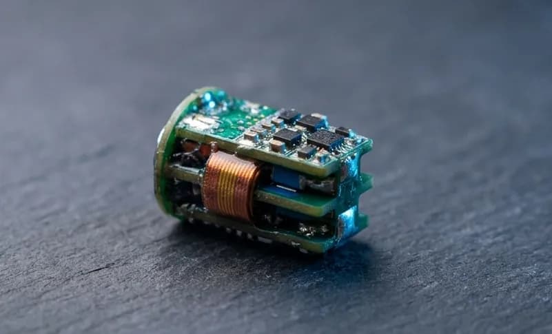
GPS Tracker Hardware Design: Modules, Power and Backhaul
GPS tracker design is a power budgeting exercise disguised as an RF problem. Almost every difficult decision traces back to how long the device must run between charges.
This guide works through the choices in the order they constrain each other.
Start with the reporting interval
Everything else follows from this number.
A tracker reporting once an hour and a tracker reporting once every ten seconds are different products with different batteries, different antennas and often different radios. Establish the requirement before selecting parts.
Ask specifically:
- How often must a position be reported?
- Does it need to report while moving only, or continuously?
- How long between charges or battery replacements?
- What is the acceptable time to first fix?
GNSS module selection
Three properties matter more than the rest.
Acquisition current and time to first fix. A cold start can take 30 seconds or more and draws full current throughout. If you wake, fix and sleep frequently, acquisition dominates your energy budget, not tracking.
Assisted GNSS support. If the module can accept ephemeris data from your backhaul link, time to first fix drops dramatically. On a duty cycled tracker this is often the single largest power saving available.
Backup power for the RTC and ephemeris. A small supercapacitor or battery keeping the module's backup domain alive turns cold starts into warm starts. Very cheap, very effective.
Small form factor modules such as the u-blox MIA-M10Q series suit wearable and compact trackers where board area is tight.
The antenna path is where fixes are won
GNSS signals arrive at roughly minus 130 dBm. There is no margin to waste.
Keepout matters. Give the antenna clear space with no copper on any layer beneath it. Treat the specified keepout in the module datasheet as a minimum.
An external LNA is often justified. If the antenna path includes a diplexer, a long trace or an RF switch, the insertion loss ahead of the module's internal LNA directly degrades sensitivity. An external LNA placed close to the antenna recovers it.
Filter before the LNA. A SAW filter ahead of the LNA prevents nearby transmitters from desensitizing the receiver. If the same device transmits at +22 dBm nearby, this is not optional.
Sharing one antenna. An LC diplexer can let a single monopole serve both L1 at 1575 MHz and a sub-GHz radio at 433 MHz. It saves an antenna and enclosure space, at the cost of insertion loss in both paths and tighter component tolerance requirements. See our guide on 433 MHz PCB antenna design for shared antenna matching.
Backhaul selection
The position is useless until it reaches somewhere.
Cellular. Widest coverage, highest power draw, ongoing data cost. LTE-M and NB-IoT reduce power significantly compared with legacy cellular.
LoRa point to point. Very low power, long range, but requires your own receiver within range. Suits closed environments where you control both ends. See our STM32WL LoRa design guide for integrated radio implementation.
LoRaWAN. Uses public or private gateway infrastructure. Low power and low cost where coverage exists. For network constraints, read our LoRaWAN device development guide.
Satellite. Works anywhere. Historically expensive and power hungry, though LR-FHSS approaches over LEO constellations have changed the economics for low data rate applications.
Many trackers use two: a primary low power link for normal operation and a fallback for out of coverage conditions. That fallback path is worth designing in early, because retrofitting a second radio means a new antenna plan.
Power budget worked through
Build the budget in energy per reporting cycle, not in average current.
For each cycle, add up:
- GNSS acquisition energy: acquisition current times time to first fix
- GNSS tracking energy: tracking current times fix duration
- Radio transmit energy: transmit current times airtime
- Sleep energy: sleep current times the remainder of the interval
- Any sensor or processing energy in between
Multiply by cycles per day, divide the battery capacity by that number, and you have your runtime.
The result is usually sobering on the first pass, and it usually points at acquisition time as the biggest lever. That is why assisted GNSS and backup power matter so much.
Battery selection
Check the datasheet under pulsed load. A cell rated for a modest continuous current may show significant voltage sag under a 200 mA transmit pulse, and at low temperature that sag worsens.
A bulk capacitor across the supply close to the radio smooths the pulse and prevents brownouts. Size it against the transmit pulse duration, not against average current.
Enclosure and mounting
Two practical points that cause more field failures than circuit issues.
Antenna orientation. A GNSS patch antenna needs to face the sky. If the product can be mounted in any orientation, either use an antenna with a less directional pattern or accept degraded performance in some positions.
Materials. Carbon fibre and metal enclosures block GNSS entirely. Plastic is fine but shifts tuning, so tune the sub-GHz antenna in the final enclosure.
Field validation
Bench testing tells you the device works. It does not tell you the product works.
Test in the actual deployment conditions: under tree cover, in urban canyons, at the mounting orientation the user will choose, at the temperature extremes, with the real battery at partial charge.
Log raw data rather than only processed positions, so failures can be diagnosed after the fact rather than reproduced.
Building a tracker that meets its runtime
Most tracker projects hit their accuracy target and miss their battery target. The fix is almost always in duty cycling and acquisition strategy rather than in component selection.
SRQ Robotics designs GNSS tracking hardware including shared antenna diplexers, sub-GHz and satellite backhaul, and power budgets validated on real hardware. Explore our PCB design services or contact us if you need a tracker that lasts as long as the specification says.