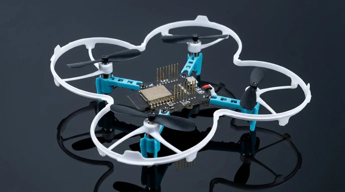
Drone PCB Design: Weight, Power and Interference
Drone PCB design differs from general embedded work in three ways: every gram matters, the power system is extremely noisy, and the whole assembly vibrates continuously.
Those three constraints drive nearly every decision.
Weight drives everything
On a small airframe, mass and flight time trade directly. Every gram of electronics is a gram of payload or battery you gave up.
Practical levers, in rough order of effect:
- Reduce board area, since the substrate itself is often the heaviest single item
- Use thinner substrate, 0.8 mm rather than 1.6 mm, where mechanical rigidity allows
- Choose smaller packages, moving 0603 to 0402 across the board
- Remove connectors, which are surprisingly heavy, and solder directly where serviceability allows
- Integrate functions onto one board rather than stacking modules with interconnects
On sub-10 gram airframes these choices dominate the design. On larger platforms they matter less and mechanical robustness becomes more important.
Motor noise is the dominant electrical problem
Brushless motors and their electronic speed controllers switch high currents at high rates. On a small airframe those currents share a supply and often a ground plane with your sensors.
The consequences show up as IMU noise, GNSS desensitization and unreliable radio links.
Separate the power domains. Give the flight controller and sensors their own regulated rail, not a direct tap off the motor supply. A separate low dropout regulator after the main buck converter is cheap and effective.
Keep motor current paths physically away from sensor sections. Route high current traces along one edge of the board and place sensitive analog and RF at the other. For layout guidelines on emissions control, see EMC compliant PCB design.
Use star grounding for the high current return. Motor return currents flowing through the sensor ground plane will corrupt IMU readings.
Add bulk capacitance close to each ESC. This keeps the current loop local rather than letting it circulate across the board.
GNSS placement
GNSS on a drone faces the worst possible environment: strong local emitters, a metallic or carbon frame, and constant orientation change.
- Mount the GNSS antenna as far from the ESCs and the video transmitter as the airframe allows, usually on a mast
- Shield the module if it must sit close to noisy electronics
- Add a SAW filter ahead of the LNA to reject out of band energy from the video or telemetry transmitter
- Never mount over carbon fibre, which blocks the signal entirely
For antenna path design, see our GPS tracker hardware design guide. Video transmitters are the most common cause of GNSS problems on drones because their harmonics can land close enough to L1 to matter.
IMU mounting and vibration
The IMU sees propeller vibration continuously, typically as strong content at the blade pass frequency and its harmonics.
Mechanical isolation. Soft mounting helps, but it introduces a new resonance of its own. If that new resonance sits inside your control bandwidth, the result is worse than no isolation. Characterize the mounted response rather than assuming improvement.
Anti-alias filtering. This matters more than most teams realize. If vibration content sits above your sampling rate, it aliases down into your control band and no digital filter can remove it afterwards. See our guide on IMU sensor fusion for motion tracking for filtering strategies.
Sensor range. Under heavy vibration the instantaneous acceleration can exceed a low full scale setting and clip. Clipped data is unrecoverable. Setting a higher range, such as 16 g, costs resolution but preserves the signal.
Power system layout
The battery to motor path carries the highest currents on the board.
- Use wide copper, and pour on multiple layers stitched with vias for high current nets
- Keep the switching loop in any onboard regulator as small as possible
- Place the current sense element carefully, since its layout affects accuracy
- Add reverse polarity protection, because it will eventually be needed
Thermal behaviour matters too. A board that is fine on the bench with airflow may overheat in a tightly enclosed airframe.
Connectors and mechanical robustness
Drones crash. Design for it.
- Prefer locking connectors on anything carrying power
- Add strain relief where wires leave the board
- Avoid placing tall components where a frame impact will shear them
- Mount with vibration in mind, since screw holes with no support elsewhere on the board will flex
Firmware and safety considerations
Two hardware decisions with safety implications:
Watchdog. An independent hardware watchdog rather than a software one. A hung processor on a flying vehicle is a falling vehicle.
Failsafe behaviour on link loss. Define it, and make sure the hardware can support it. Motors must reach a known state on loss of control input.
Where drone electronics projects go wrong
- Designing for the bench rather than for the vibration and noise of flight
- Discovering IMU noise only after the control loop is tuned
- Mounting GNSS near a video transmitter
- Missing the weight target because connectors and substrate were not budgeted
- Clipping the accelerometer at a range chosen for resolution rather than headroom
Getting UAV electronics right
Most drone electronics problems are noise and vibration problems that only appear in flight, which makes them expensive to find late.
SRQ Robotics designs UAV electronics from micro airframes upward, including flight controller hardware, IMU integration under vibration and RF coexistence between GNSS, telemetry and video. Learn more about our PCB design services or contact us if you have a platform that behaves on the bench and not in the air.